|
Line Detection |
  
|
| Show/Hide Hidden Text |
|
Line Detection |
|
| Show/Hide Hidden Text |
Warning : This is a very CPU and Memory intensive process. Depending on your settings it will make your computer work very hard!
The line detection function is an experimental feature to try to detect linear shapes in processed images. There are various settings relating to this feature, the ones relating to the actual detection are:
| • | Detection Aggressiveness: This will determine at what brightness level the application will look for lines. 20 is a good starting value. |
| • | Min Length: The minimum length in pixel a line feature must reach to be identified as a line feature. A setting less than 20 will lead to an increase in false positives. |
| • | Max Line Break Occurrence: The number of times a line feature can be interrupted by a dim pixel below the aggressiveness threshold and still be classed as a line feature |
Please note that there is a balance between trying to find the most line features vs. the time taken to find them and the number of false positives detected. You can experiment to find your ideal settings but a good starting point is:
| • | Aggressiveness: 20 |
| • | Min Length: 20 |
| • | Max Line Break Occurrence: 1 |
Prevent Line Detection during Daylight
Some users will also have their camera running during daylight hours. As line detection is not useful here it can be stopped by setting the following settings:
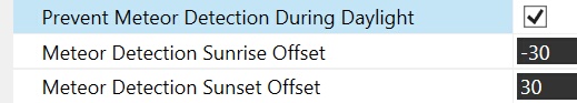
Once set, the detection function will start at sunset and stop at sunrise (+- set offsets).
Detection Output
All files created by the detection function are saved in the 'Detection Output Folder' defined in the settings. When a line feature is detected an image will created not only containing the image of the processed picture but also the image immediately before and after the processed image (this can be suppressed in settings if the previous and following image are not required). Additionally (if desired) a detection circle will be drawn around the detected line feature:
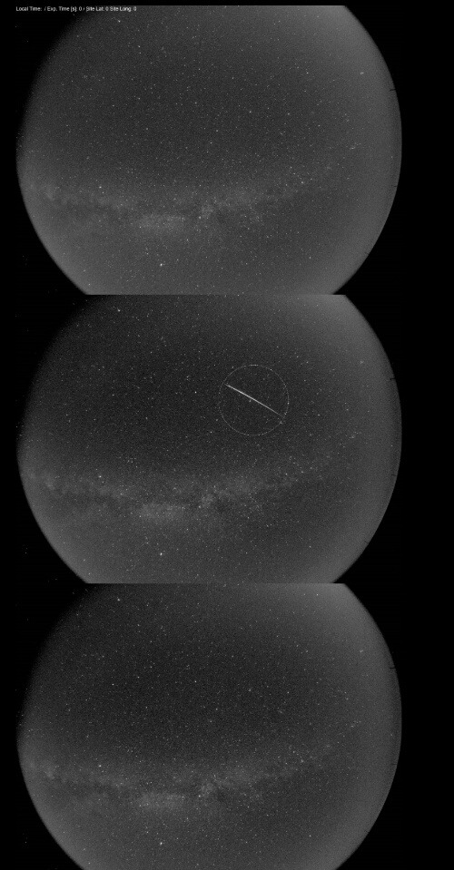
This makes it possible to immediately see if the line forms part of an airplane or satellite trail or wether its confined to just one image. The image can also contain a text overlay as specified in the settings but please note that this information relates to the centre image.. The output type (jpg/png) can also be specified in the settings (as well as jpg quality in case of jpg output).
Original FITS File:
The line detection function also contains a features to copy the original FITS image to the detection folder as well if a line feature has been found. This can be useful to further examine the line feature in full resolution.
FTP Transfer:
Detection images as shown above (but not the original FITS images) can also be transferred via FTP if detection settings are provided accordingly.
Applying a Circular Mask
For detection it is possible to apply a circular mask i.e. only run the detection inside a circle determined by the settings. This is useful if you have a camera picking up terrestrial features at the edge of the imaging circle. This often leads to false identification of line features especially if light pollution spills into the image. To define the mask you need to supply the following values (all in pixel) in the detection settings:
| • | Mask Centre Point X coordinate value |
| • | Mask Centre Point Y coordinate vallue |
| • | Mask Radius |
A 'mask indicator circle' will be drawn in a dotted line to indicate the area that has been searched for line features.
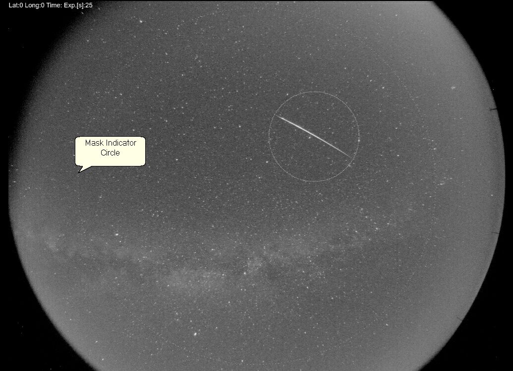
Detection Mask Sample
Reject Repeating Lines
Often bright features like the moon, planets or artificial light can cause line like features to occur in multiple images. It is possible to reduce such 'false positives' by enabling the 'repeat line rejection' feature working on the assumption that a meteor will not appear on two consecutive images.
| • | Reject Repeat Lines Time Window: The time window to compare line features to i.e. if any line features have been detected in a similar spot in the set time window previous to the acquisition it will be rejected |
| • | Reject Repeat Lines Pixel Overlap: The maximum distance in pixel a line feature can be removed from a previous line feature to be considered for rejection i.e. if a previous line feature is within this pixel range of the line feature that's being checked it will be rejected |
This feature obviously assumes that no two meteors will be occurring in the same location within the set time frame. It is therefore probably best to tone down or disable this feature during times where the likelihood of meteors occurring is high e.g. during a meteor shower.
Rejecting Airplane / Satellite Trails
Airplane or satellite trails will most likely be detected as line features. The 'Reject Airplane Trails' feature can reduce 'false positives caused by such trails by comparing line features in the previous and subsequent image and check if the line features match up and for a trail. This relies on the fact that an airplane trail will be seen in more than one image and conversely that a true meteor line feature will NOT be visible in more than one image. This is a reasonable assumption as downloading and initial processing of an image will take longer than the passage of a meteor.
There are three parameters governing this rejection;
| • | Pixel Gap: The maximum number of pixels two line features can be removed from each other and still be classed as a continuing trail. This is required to bridge the gap where one image exposure finishes (and the image is downloaded) until the next exposure begins. Please bear in mind that setting a pause in between exposures will obviously increase this distance or make use of this feature useless. |
| • | Angle Change: The maximum angle change in degrees between the two lines. Normally airplane trails do not change direction very much is they are flying high but if you live under an airport flight path you will need to increase this to account for turning aircraft. |
| • | Max Time Gap between images: Multi image trail rejection only works if images are taken in quick succession. This setting determines how much time can pass between exposures of two images to still run this feature. This time should account for downloading, initial processing and creating of the FITS image in the acquisition folder. Please note that any set 'Pause' between exposures is already accounted for in the calculation and should NOT be included here. |
Please not that airplane trails are not always detected to their full extend and it's therefore still possible for trails to slip through this feature. For this reason the detection images contains all three images and allow you to quickly see if the line feature forms a trail in the image before or after.