|
Star / Planet Overlay |
  
|
| Show/Hide Hidden Text |
|
Star / Planet Overlay |
|
| Show/Hide Hidden Text |
When enabled this function will overlay labels and markers onto output images to annotate stars and solar system objects that should be visible on the image. This overlay can be applied in three functions:
| • | Preview Image (by using the tick boxes above the preview image) |
| • | Latest Image (activated in settings) |
| • | Image Conversions (activated in settings) |
The basic mechanism to create this overlay works as follows:
| • | The application doesn't know what's on the acquired image - there is no plate solving involved it only calculates what SHOULD be there |
| • | As a starting point the app determines the current zenith position of the imaging location based on entered latitude and longitude and current date and time |
| • | The app then runs through the loaded star catalog and solar system objects and for each object determines the current altitude and azimuth based on the entered imaging location and current date and time |
| • | If the object is above the horizon, the app will use the entered mapping function to calculate the distance and angle of the object from the calculated zenith position and determine the X and Y cooridnates of that point on the image |
Star Catalog File
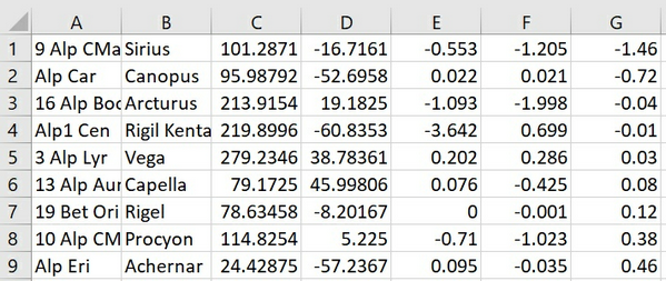
The application needs a star catalog to extract star data for stars that should be shown on the output images. The application will come with a built in catalog but it's very easy to supply your own if desired. The file is basically a 'comma separated values' (.csv) file and MS Excel is usually the tool of choice to create or modify those. If you do not supply a star catalog file in the settings shown above then the built in catalog will be used. If you want to build your own, the required format is:
| • | Column 1: Star name -> Will be used if no common name is entered |
| • | Column 2: Star Common Name -> Used for label if supplied |
| • | Column 3: Right Ascension in Decimal Degrees |
| • | Column 4: Declination in Decimal Degrees |
| • | Column 5: Annual Proper Motion RA -> Will not make much of a difference for this purpose so if not to hand just set 0 |
| • | Column 6: Annual Proper Motion DEC -> Same as above |
| • | Column 7: Apparent Magnitude |
All data should be entered for J2000.
Sample as seen in Excel:
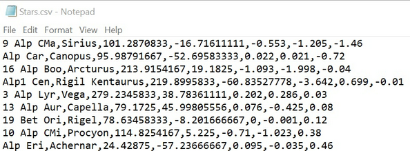
Sample as seen in Notepad:
Display Settings
The star overlay has the following display settings:
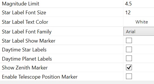
| • | Magnitude Limit: Only stars above the given magnitude limits will be labeled. |
| • | Font Size / Color / Family -> The size, color and family of the font to be used |
| • | Show Marker -> If ticked a small marker will be shown at the calculated star position. This is unlikely to be precise for all shown stars and can be confusing to look at so probably only really useful for setup purposes. |
| • | DayTime Star labels: By default star labels will be hidden during daytime. You can choose to display them by ticking this box. |
| • | DayTime Planet labels: By default planet labels will be hidden during daytime. You can choose to display them by ticking this box. |
| • | Show Zenith Marker: If ticked the Zenith will be marked by a lebel |
| • | Enable Telescope Position Marker (PRO): See Telescope Marker for details |
Star Overlay Setup - ALL VERSIONS
The AllSkEye app comes with a convenient interactive way to setup the overlay mapping by identifying known star in an image.
| • | For full details on how to setup the star overlay please see: Star Overlay Tab |
| • | Once complete the required parameters will automatically be saved to the settings |
| • | You can ignore any of the further instructions on this page. |
DEPRECIATED - WILL BE REMOVED IN FUTURE VERSIONS
Instructions below are no longer in use as of version 0.9.25.0. Please use instructions above to setup star overlay.
Normal Version Setup - Required Settings:
To setup the star overlay manually, you have to enter the following settings. Each of them is explained in much greater detail below:
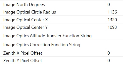
Image North Degrees
This value should accurately describe the angle between a vertical line through the image Zenith point and a line running from the zenith point directly north, measured in a clockwise direction (e.g. if you live in the northern hemisphere and have sight of Polaris a line from the Zenith to Polaris). You can either do this on a printed image or by use of a image manipulation tool which allows the measurement of angles. Again we can use the GIMP image manipulation program. The require steps are:
| • | Locate the image Zenith point by looking up the Zenith position in an astronomical application (I used SkySafari) for the same latitude, longitude and exact time the image was taken |
| • | Then locate a point on the image at the edge which points towards north. In my example I have identified Polaris |
| • | Draw a vertical line through the Zenith point |
| • | Draw a line from the Zenith point to the North marker point |
| • | Measure the angle between the vertical line and the north marker line (0 to 359.99) in degrees |
| • | In my example below I have used the GIMP measure tool to draw this line. This gives me a popup box which shows me the length in pixels as well as the angle. In GIMP the angle is give against a horizontal line so if we use this we need to calculate 90 minus the angle that is displayed i.e. 90 - 41.04 which gives me 48.96 degrees |
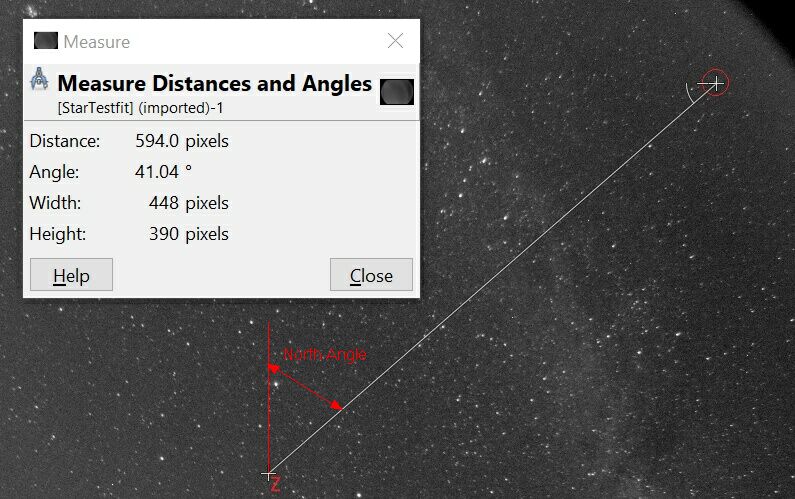
Image Optical Center
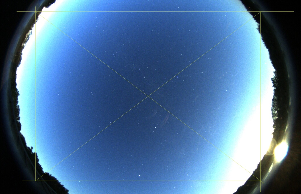
In an ideal world the optical center of the lens would coincide with the center of the camera chip and therefore the center of the created image. For some cameras this might be close, for others it could be way off, especially if they are full 180 degree lenses which leave a lot of space surrounding the actual image. So it is necessary to work out the x and y coordinates of the optical image center (measured from the top left corner) to allow the app to place the overlay correctly. To roughly work out the optical image center, ideally you will have some sort of indication of where the image circle is on the image. This will be easier for 180 degree lenses where the entire sky and surrounding edges are shown on the image. Here you can estimate the center by trying to find the center of this circle as accurately as you can.
Finding the optical center is probably easiest by using an image manipulation program which allows the readout of x and y coordinates of selected pixels. For example I have used Gimp to draw a rectangle into the shown imaging circle and used the corner diagonals to find the center point (there are various methods of doing this). Hovering over the center point allows me to readout the x and y coordinates of that point at the bottom of the GIMP window. These values (x und y from the top left corner) should then be entered as 'Image Optical Center X' and 'Image Optical Center X' in the general settings section.
For setups that do not show the image circle it might be more difficult to work out where the optical center is.Maybe it might be possible to mark a point on the Perspex or adjust the lens to see some of the image circle. If you find a good way please let me know!
Image Optics Transfer Function Points String
The series of points set here will tell the application how to convert the altitude of an object into number of pixels from the zenith point. It basically describes how your optics project the incoming light onto the camera sensor. Because the application is used by many differing imaging systems it would be difficult to define a mathematical function to describe this relationship so I have instead opted to calculate this by measurements and interpolation. The basic idea is that you define a string which contains pairs of values which describe a point on the image where:
| • | Value One is the sky angle from the optical center point to the chosen reference point |
| • | Value Two is the distance in pixel from the optical center point to the chosen reference point |
So for example for my Oculus camera, starting from the center of the image I have determined the following values:
| • | First reference point is 0,0 -> at the center the distance is 0 pixels (this must be added) |
| • | Second reference point 9.7,97 -> at an angle of 9.7 degrees from the image center to the reference point the distance is 97 pixel |
| • | Third reference point 22.3,216 -> at an angle of 22.3 degrees from the image center to the reference point the distance is 216 pixel |
| • | etc. |
The format of the string that needs to be set in the general settings is to separate the values in a pair with a comma and to separate the value pairs with a semicolon: AnglePointOne,PixelDistancePointOne;AnglePointTwo,PixelDistancePointTwo;AnglePointThree,PixelDistancePointThree and so on
For example the values I have determine will result in the following string:
0,0;9.7,97;22.3,216;42.5,403;55.5,515;69.8,635
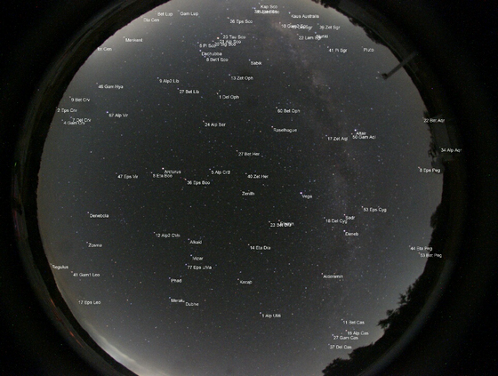
How to obtain Values
The values of pixel distance and angle need to be obtained from an image you have taken with your setup. It's probably easiest to work with a jpg or png image, you can get such an image either through the 'Latest Image' function or through the 'image conversion function'. You can then open the image in an image manipulation program to obtain values. There are many way s to do this but I found it easiest to draw a line from the center to the edge which passes through a series of well defined stars. I then mark a a number of points on that line which correspond to nearby stars that I can identify in an astronomical application. For each of these point I then obtain the angle and distance from the center.
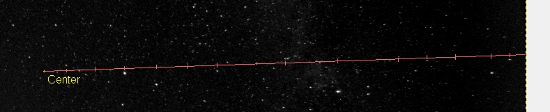
The distance is easy the get by using a measuring tool in the image manipulation application such as GIMP:
![]()
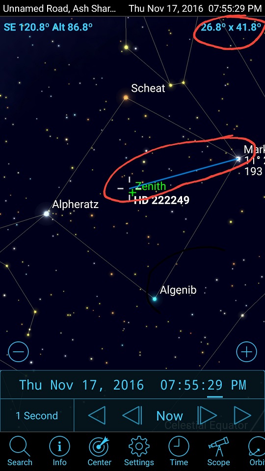
The angle is a bit more difficult to obtain. You basically have to use an astronomical application which allows you to measure the sky angle between two points or stars. Open this application and set the location, date and time to the location, date and time the reference image was taken (if you have the FITS image file you can read this from the FITS header). You then have to identify and mark the center and reference point from the line above and readout the angle value. SkySafari for example lets you do this quite easily.
Sky Angle Approximation:
There is an easier method to obtain this angle if you assume that your optical center point is co-located with the Zenith point i.e. your camera setup is pretty good. In this case, if you use an astronomical app and display the night sky for the exact location, date and time the image was taken at, you can read the reference star altitude and just calculate:
Angle = 90 - Altitude
This method will probably be sufficient for most setups to obtain a reasonable approximation.
Image Optics Correction Function String
I have found that for various reasons the calculated angle value to place a star marker on the image can vary slightly from the actual angle of the the star on the image image (especially if the optical center is offset form the Zenith position - see next point). This angle difference, although small (on my setup usually between -1 and 1 degree) is not uniform and different segments of the circle need different small adjustments. You can easily get a feel for this by showing the star markers on an output image and looking at the star marker vs. the actual stars. If you find that certain angles on the image all have a certain angle offset then this function is for you. If you are only looking for a reasonable approximation then this is probably not required (it's fine tuning).
Please note that if you find that ALL stars are offset by the same value then it is your 'Image North Degrees' settings that needs to change!
Again I have employed a correction string that has a similar format to the Image Optics Transfer Function Points String (see above) where you supply value pairs with the following values:
| • | Value One is the angle on the test image (measured from the vertical in a clockwise direction) |
| • | Value two is the angle adjustment (in degrees) that should be applied at the angle position |
For example if you find that on your test image all stars at roughly a 45 degree angle (from the vertical) are about one degree ahead of the displayed marker then you can supply a value pair of: 45,1. This will move any marker at a 45 degree location on the image by one degree around the zenith position. Once value however is not enough as there needs to be a gradual change from one angle to the next to allow any intermediate positions (which don't have a dedicated correction value) to be interpolated. So if you are using this feature I would suggest that you provide values for at least the cardinal points but better at least every 45 degrees. So you could end up with a string such as this:
0,0;45,0.5;90,1;135,0;180,-0.5;225,-1;270,0; 315,0.5
So with this example at 0 degrees no adjustment will be applied. At 45 derees an adjustment of 0.5 degrees will be applies. At any angle between 0 and 45 degrees an interpolated value between 0 and 0.5 will be applied and so on. You can see that the more values you provide, the more accurate the adjustment becomes.
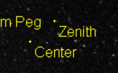
Zenith Offset Adjustments
A further adjustment can be made to try to correct the error introduced by the fact that the image optical center might not be aligned with the actual zenith (overhead) point for the given location, date and time. You can easily determine what the error is by looking at a test image which shows the image optical center. Then identify the approximate location of the actual Zenith point by looking at an astronomical application showing the night sky for the same location, date and time. On your test image mark this zenith position. Once you have both positions marked again use an image manipulation program to measure the X and Y distance in pixel from the center point to the zenith point (where right and up are positive values, left and down negative):
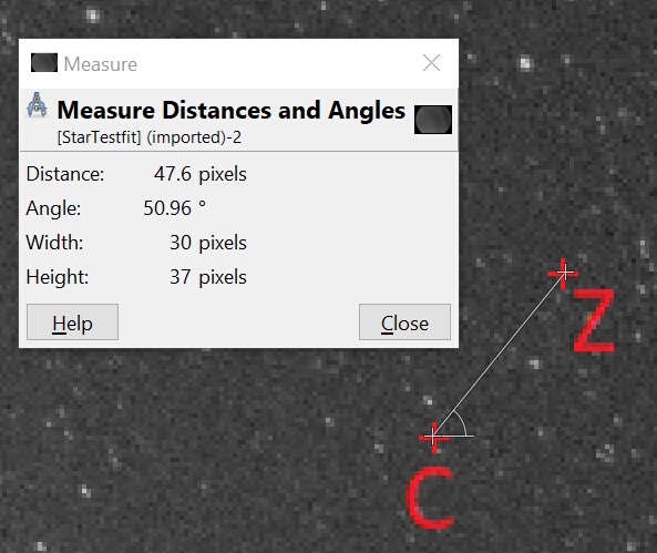
Here for example the pixel offset between the center and zenith point is:
| • | X -> 30 |
| • | Y -> 37 |
Now that you know this error you can either:
| • | Try to physically make an adjustment to your camera fixing to try and point the camera more towards the Zenith (if the error is large, I found that small errors are difficult to correct) |
| • | Set these values as the 'Zenith Offset Adjustment' values in the general settings. This will try to take the offset into account and adjust accordingly. |
If you have made an adjustment you can easily check if it has been applied correctly by selecting to show the center point on a test image (the app will also show the zenith point by default). The zenith point should have now moved by the given adjustment and be at the location that you have specified: